Idea
The family was excited to decorate to halloween this year, and several of the decorations came with Try Me buttons. The buttons were external to the decoration - and seem to be simple momentary switches (when they are pressed the circuit is closed for the duration of the button press).
It would be neat to add these to our programmable space using a tiny ESP-8266 microcontroller / MQTT.
Based on success of connecting Miffy to our local programmable space, this seemed approachable for an electronics novice like me.
Watch the video below to see what happens when the button is pressed - a loud cat meow / head movement.
I love the idea of ESP-01. For less than $1 you get a tiny ESP-8266 board - with WiFi that can run MicroPython. It only has a few GPIO lines, but one should be enough??
Conceptually it seems simple enough - somehow simulate a press button event using the GPIO. But does that mean I need resistors, transistors, memristers, mosfets, relays???? (have I meantioned I am not a master of electrons)
Naive Approach - Fail
Readers, this did not work…
Perhaps I can just use high/low (voltage) of the GPIO.
Perhaps start with the naive thing. As long as I don’t ruin Halloween by “bricking the cat”, let’s try the simplest thing. No worries if I ruin a few ESP microcontrollers.
Reading the micropython tutorial on GPIO pin, it is pretty easy to have a very simple on/off loop:
import machine

pin = machine.Pin(5, machine.Pin.OUT)

while True:
    pin.value(1)
    time.sleep(0.1)
    pin.value(0)
    time.sleep(0.1)
Micropython on ESP-01
Unlike fullsize ESP-8266 devices which have USB (device profile) built-in - for both serial IO and programming - the smaller ESP-01 devices need a special usb breakout cable (FTDI I think) to flash/communicate with them.

I actually needed both a USB-FTDI cable and a 3.3v power source (as my USB FTDI provides only 5v). After wiring together a simple connector, I was able to flash the device:
By following along with micropython tutorial
To setup, first I needed to install python3-pip, then pip install esptool
Then I can delete old firmware.
% esptool.py --port /dev/tty.usbserial-0001 erase_flash

esptool.py v3.1

Serial port /dev/tty.usbserial-0001

Connecting...

Failed to get PID of a device on /dev/tty.usbserial-0001, using standard reset sequence.
.
Detecting chip type... ESP8266
Chip is ESP8266EX
Features: WiFi
Crystal is 26MHz
MAC: a0:20:a6:02:01:e9
Uploading stub...
Running stub...
Stub running...
Erasing flash (this may take a while)...
Chip erase completed successfully in 8.1s
Hard resetting via RTS pin...
After this I can flash micropython bin that I previously downloaded
% esptool.py --port /dev/tty.usbserial-0001 --baud 460800 write_flash --flash_size=detect 0 esp8266-20210902-v1.17.bin
esptool.py v3.1
Serial port /dev/tty.usbserial-0001
Connecting...
Failed to get PID of a device on /dev/tty.usbserial-0001, using standard reset sequence.
.
Detecting chip type... ESP8266
Chip is ESP8266EX
Features: WiFi
Crystal is 26MHz
MAC: a0:20:a6:02:01:e9
Uploading stub...
Running stub...
Stub running...
Changing baud rate to 460800
Changed.
Configuring flash size...
Auto-detected Flash size: 4MB
Flash will be erased from 0x00000000 to 0x0009afff...
Flash params set to 0x0040
Compressed 633688 bytes to 416262...
Wrote 633688 bytes (416262 compressed) at 0x00000000 in 10.8 seconds (effective 471.2 kbit/s)...
Hash of data verified.

Leaving...
Hard resetting via RTS pin...
At this point I should be able to connect to the REPL (python interpretter) from my computer using screen
unfortunately I can’t remember how I get the TTY console to work on the ESP-01 once it reboots… It seems like my baud rate is incorrect or something…
screen /dev/ttyUSB0 115200
After trying too long, I decided to switch to fullsized ESP-8266, as I just have to plugin a standard USB cable between the microcontroller and my computer.
Some progress with ESP-8266
A fullsize ESP-8266 has more storage, built-in USB (for both power and interfacing with a computer). I have used it successfully to control Miffy via MQTT.

Less than a minute from plugging in USB on full-sized #esp8266, I was able to flash and install #micropython, and get a working REPL
screen /dev/ttyUSB0 115200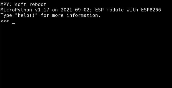
At this point I was able to test if the naive approach of using high/low GPIO directly to simulate closing a circuit would work.
Using the code above I alternated high/low to a GPIO pin every second.
Then I tried every combination I could think of for how to connect the microcontroller pins directly to the button input for the decoration.
Good news: the cat still works as expected when not connected to the microcontroller (this is the most important!)
Bad news: nothing I did was able to simulating the button push.
A New Hope
In chatting with Quinn Scripter, he was suggested that since the button is momentary it probably isn’t carrying the power the cat uses to perform its actions (as evidenced by the the fact that the cat continues to meow/move after the button is pressed). He gave me some tips about transistors/mosfets - and since it doesn’t seem like much current flows through the button, a simple transistor might work.

Using “Open Drain” with GPIO
After a failure to use an unlabeled transistor I had in my box of parts, I was read-reading the Machine Pin docs for micropython. I noticed a mode for a GPIO pin:
Open-drain output works in the following way: if the output value is set to 0 the pin is active at a low level; if the output value is 1 the pin is in a high-impedance state. Not all ports implement this mode, or some might only on certain pins.
My (novice) brain interprets that to say:
    # 0 - the pin is active at a low level
    if pin.value == 0:
        pin.connect(ground)

    # 1 - the pin is in a high-impedance state
    if pin.value == 1:
        pin.connect(None)
I think this means by replacing the cat’s “try me” button with a wire to my microcontroller’s ground and a wire to a GPIO pin in “Open Drain” mode - I can set the value of the pin to 0 mometary to trigger the cat!
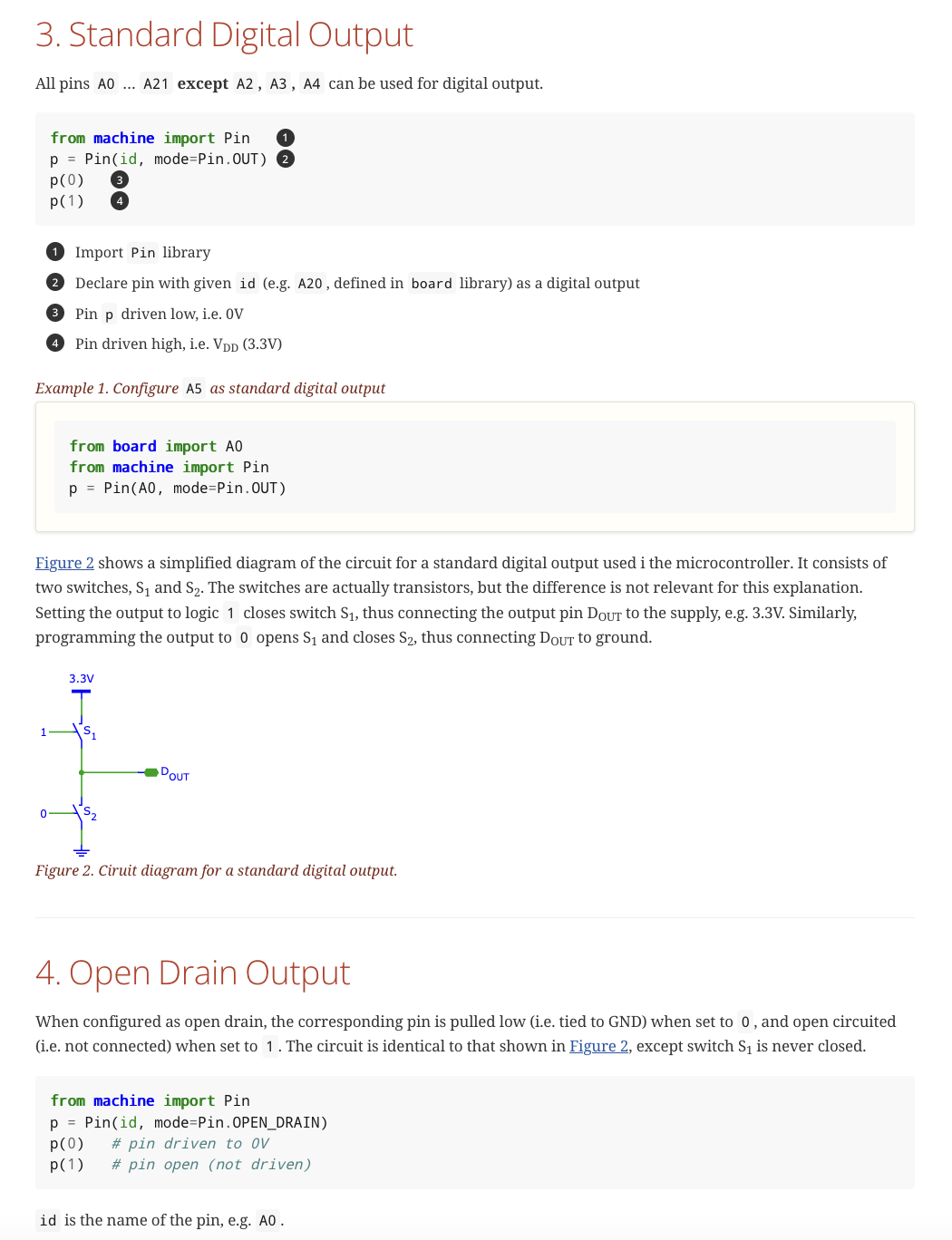
I found these IoT49 notes by Bernhard E. Boser useful - in showing how Standard Digital Output as well as Open Drain Output work with microcontrollers and micropython!
screenshot of notes on digital gpio / open drain for posterity

With that done, I can setup the pin in the proper mode (defaulting to “open” / unconnected), then connecting it to ground for 100ms when I want to trigger the cat!
import time
import machine

tryme = machine.Pin(5, machine.Pin.OPEN_DRAIN, value=1)

def press_button(t=0.1):
    tryme(0)
    time.sleep(t)
    tryme(1)

press_button()
It works!
When the GPIO button’s value gets set to 0, then both wires from the cat are connected to the microcontroller’s ground. Closing the cat’s button circuit! (at least that is what I think is happening to triggers the cat’s meow)
Open Question(s)
Yes it works, but…
All the time one of the wires from the cat is connected to the microcontroller’s ground. And for 100ms whenever the pin is set to value 0, both buttons are connected to ground.
Is there any issue with current from the cat damaging the microcontroller?
Is there any issue with always having one wire connected to the microcontroller’s ground - in that it might be allowing electrons to flow from the cat to the microcontroller?
Next Steps?
Connecting the device to the wifi network and mqtt should be very similar to Miffy’s code. But before I do that, I want to learn more about any bugs in my approach using “open drain”